Please Note

Visitors are kindly requested to give valuable feedback. The feedbacks always helps me in correcting issues and modify and improve the site to its best

Wednesday, August 1, 2012

VFD Panel : Protective Switchgears

In my Previous post I just have mentioned the basics fundemental facts regarding AC Drive panel
In this article is shall discuss

  • the various protective switchgear available 
  • what all configuration we can opt
  • how to choose protective switchgear
Isolation
Mainly in almost all industries there will be a MCC panel for various motors installed. When separate drive panel to be provided a power isolation to be included in the panel
mainly we have following options
  • SDF
  • ISOLATOR
  • MCCB
  • Power contactor
 Now Using SDF is convention practice, but now a days customers prefer MCCB to SDF. While ordering MCCB should also order the door mounting kit if you want to operate the device from door.

Now is the incomer supply needs to be controlled remotely then we use Powercontactor and it is switched by proper control loop.


Semiconductor Fuse

For Power Electronics based switching devices it is always good to include
thyristor fuse at the incomer. Now when compared to HRC fuses, thyristor fuses are much more costlier.

while ordering fuse, you have to be careful in selecting fuse and its base.different type of fuses are available in the market.

most of the manufactures in their vfd catalogue have mentioned the details of
appropriate switchgear to be used along with particular drive. once you get the specification you can opt for different make if price does matter

I shall include some selection chart in the next post and shall explain with examples  " how to select right switchgears"


Monday, July 30, 2012

Designing AC Drive Panel: Basics

VFD/Inverter panel  essentials


In this post I shall enumerate the basic requirement, design aspects, electrical aspects of vfd panel

we all know that now a days with the extensive developments in the field of power electronics
now vfd application to induction motor is now a common practice. Now in the market application specific drives are available with sophisticated control features.

Now whatever the drive make is , there is some general standards to be followed for
selecting the right switch gear
selection of filters, reactors and smoothening circuits
cable sizing
cooling clearance
arrangement of modules
panel cutout
glanding
control wiring etc
We can supply the panel with the way we want. But its not the right method. One who designing the entire system should have a good knowledge
motor load type/ Application
Ambient conditions where the motor and panel will be fixed
Total distance of power cabling
The way the cable to be routed
The IP standard to be followed

While executing the project the concerned engineer must understand client's exact requirement and should prepare the drawings and layout based on that.
Now even though the drive has got inherent ability to respond to faulty conditions, its always recommendable to go for protective power components. The most common include

sdf/mccb at incomer : mainly meant for supply isolation

HRC fuse
Thyristor fuse
Line reactors, Line LC Filters
Output reactor : if requred
Braking components : if required
Power cable selection


Line reactor selection

The equation for the reactance of an inductor is
XL = 2¶FL. Where XL is inductive reactance in Ohms, F is the applied frequency of the AC source and L is
the inductance value of the reactor. As you can see, the reactance and therefor the impedance of the
reactor is higher with a higher inductance value. Also, a given inductance value will have a higher
impedance at higher frequencies. Thus we can say that in addition to limiting the rate of rise in current, a
reactor adds impedance to an AC circuit proportional to both its inductance value and the applied
frequency


Now while selecting the filter components you should be always careful because wrong selection will result in adverse results, but from my past experiece what I understand is that if you once got the concept, if you know the electrical aspects then you can go ahead.

since the inductance is in series in the power circuit  ofcourse a small percentage of the applied voltage would drop across. 
the drive manufactures in their product catalogue mostly mentioned the specification of the suitable line reactor.
once you got the specification you can check for other make too.

This topic is not over, shall update further in coming days
those who read, if find that the post is informative please provide your valuable feed back. this would certainly help me in improving over the upcoming posts




Monday, August 29, 2011

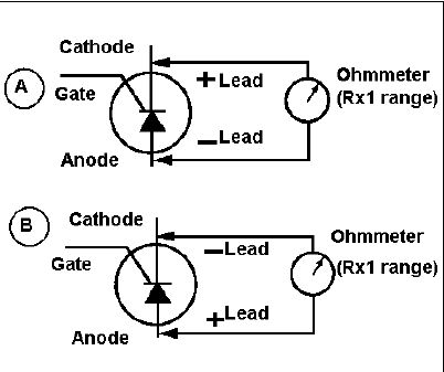
How to check healthyness of Thyristor

The basic methods available to check thyristor is mentioned below

  • put the multimeter in resistance mode(auto scale)
  • measure resistance across anode(A) and cathode(K) ; reading should be more than 100k if thyristor is healthy
  • in most cases when thyristor fails , it gets shorted
  • Resistance across Gate(G) and Cathode(K) should be in the range of few ohms


more details available in below mentioned link

Friday, August 26, 2011

v/f control scheme- basic concept

For controlling the speed of induction motors in various industry application variable frequency control drives are used
One of the main speed control scheme used is the v/f control mode
here i shall explain briefly why v/f control, why this ratio is to be maintained and all
before reading this blog i recommond  you to go through the basic working principle of induction motor

v/f control

we know the expression for synchronous speed Ns
Ns = 120*f/P..................(1)
where
f: frequency of supply voltage
P : No of Poles

for a given induction motor no poles is constant, so inorder to change the speed , supply frequency need to be changed, now the question is then why to change voltage too? whats the big deal in maintaining the v/f ratio?
here is the answer for it

we know the that the motor torque developed  , T is directly proportional to both flux Φ and Current I
ie T= constant *Φ*I.........................(2)

now the expression for induced emf in the rotor of induction motor

E = 4.44FZΦ.........................(3)
where z is total no of conductors
from this equation

Φ= E/Φ

approximating E to terminal voltage V

we get that Φ= V/Φ

Now in most motor applications the torque is to be maintained constant
if we change frequency alone, then the torque requiremens will not be met (check eqtn (2)
So at particular load, in order to get speed control along with maintaining the torqe, v/f ratio to be maintained


Wednesday, February 9, 2011

Industrial Automation-OPC Server

Hi all

This blog is focused on Industrial automation side, especially on industrial communication. Here I am discussing concept of OPC server

For those who new to the field of automation, I shall just explain what is a OPC server
  • From various Input/Output devices , PLCs and Controllers, we need to fetch and transmit data. data may be digital or analog. so communication need to be established between the field devices and Computer.
  • Once the devices are connected to Computer via proper industrial communication mode [eg profibus, industrial Ethernet, HART, etc] next step is to access those data to a scada or dcs] here comes the role of OPC server]
  • OPC[ OLE of Process Control] helps in communicating with those device drivers and some other scada/ database/ server etc..
  •  Before you go on deeply to OPC and its working, you should have the basic knowledge of whats a database how a database server works and all. After gaining enough knowledge on those, then it will easy for you to learn the working of OPC server. There many OPC servers available on market
  • Recently I came across this Kepware . I worked on its demo version, and i found that it is very simple to use
  • The Kepware supports many existing branded industrial I/O devices 
Follow following links if you wish to know more about OPC server
http://www.opcfoundation.org/
www.kepware.com
Iam working in the field of Industrial Automation, and here through this blog  I am aiming at sharing the knowledge/things I learn , In the next blog  I will be discussing the opc little more deep, also i will share basic concepts of PLC

Those who read please provide the valuable feedback, also post your comments.
                                                                                     -ppk-